Lifting Machine Design Project
Lifting Machine Design
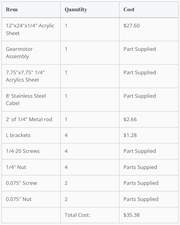
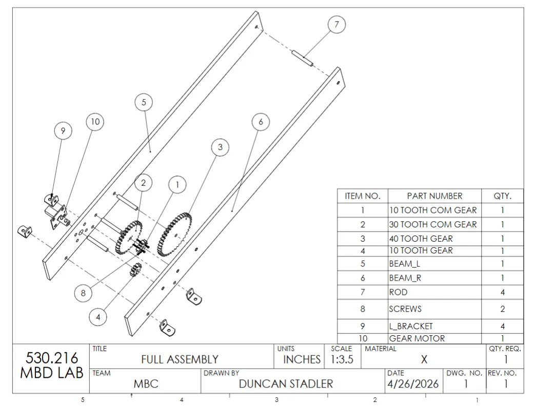
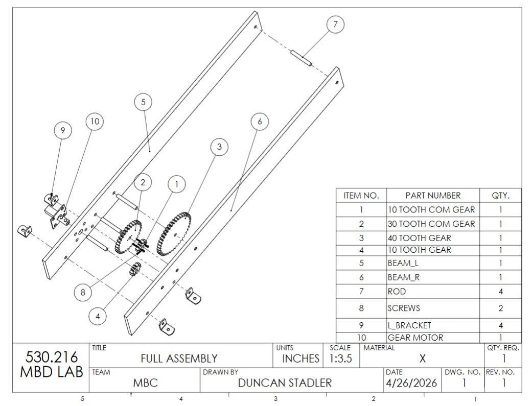
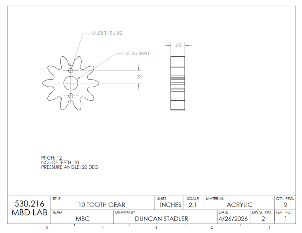
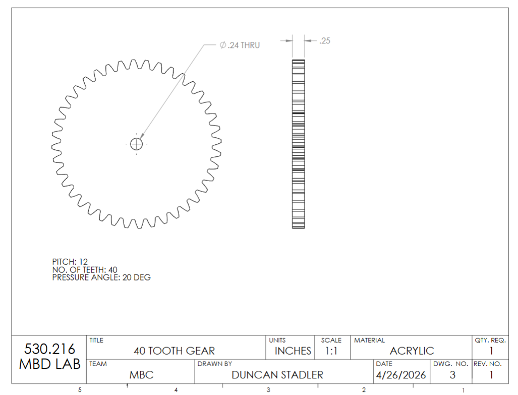
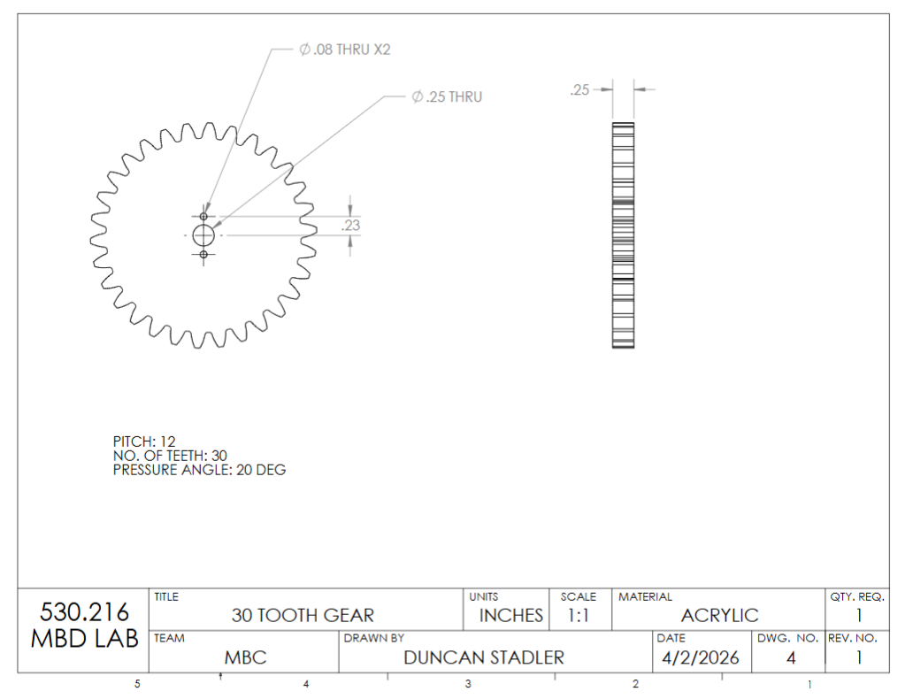
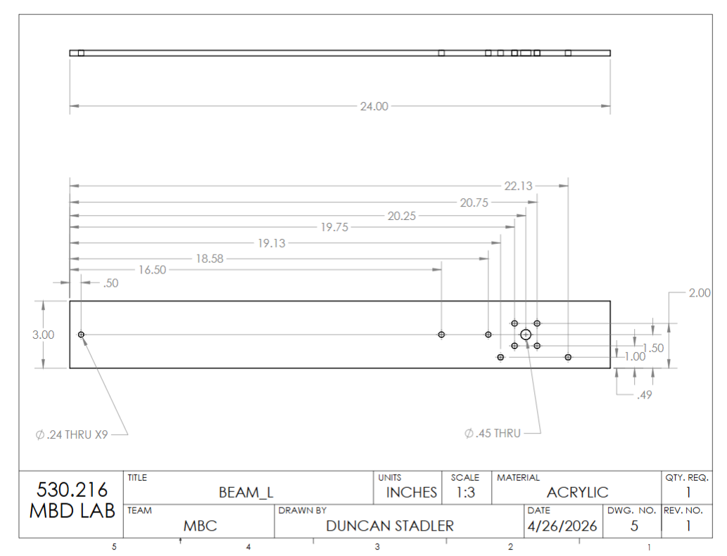
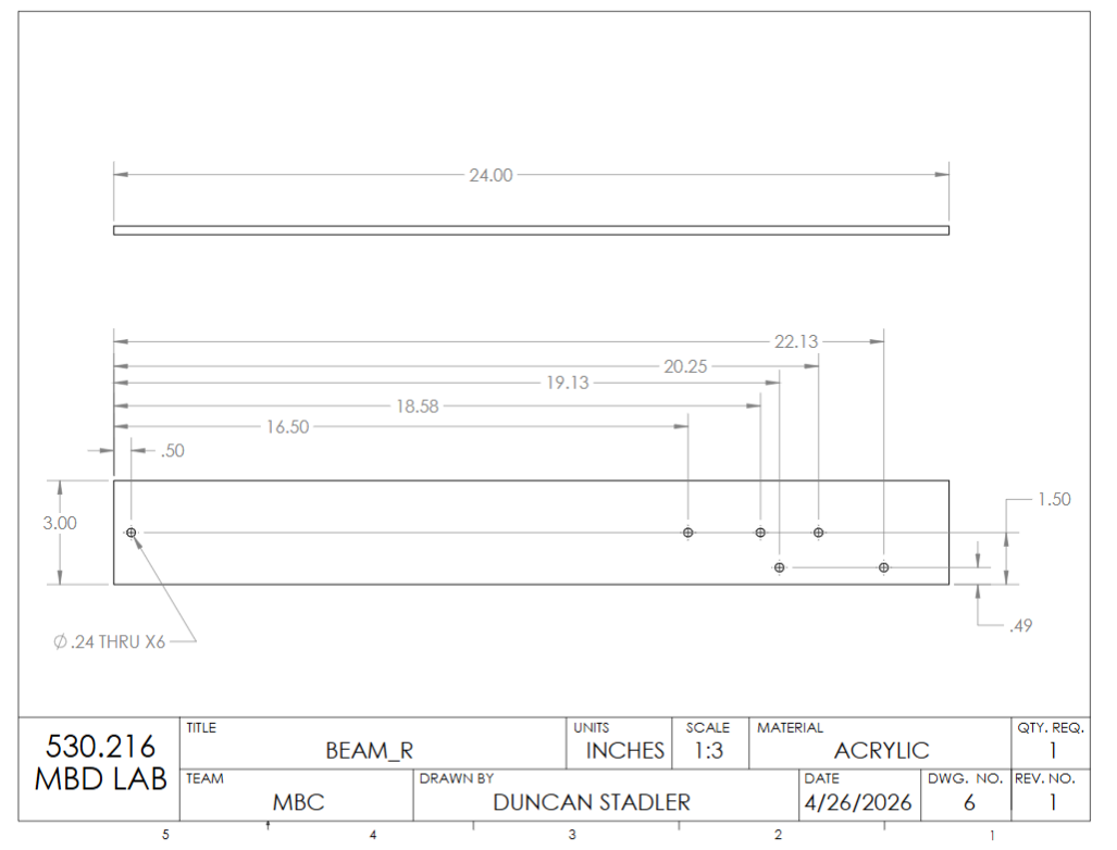
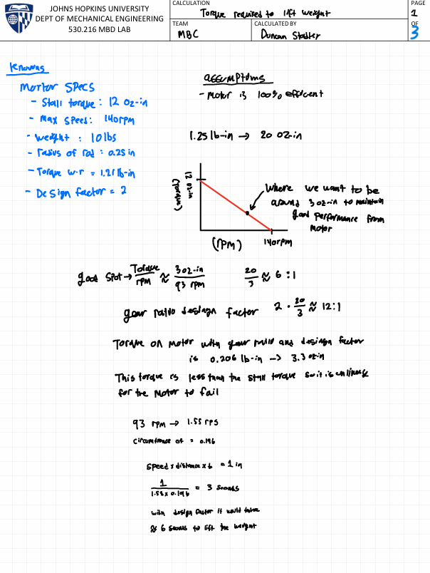
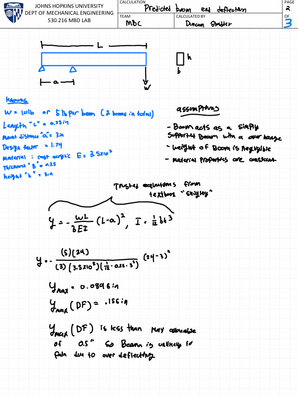
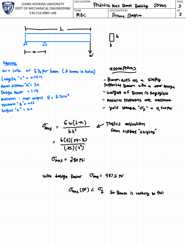
The lifting machine was designed with a 12:1 gear ratio. This ratio was achieved through a transmission system containing four gears, two ten tooth gears, a thirty and forty tooth gear. The thirty and one of the ten tooth gears were attached creating a compound gear. The beam was two feet long, extending eighteen inches past the edge of the table where it was mounted. The mounts were four small L brackets spaced three inches apart. There were two beams each with a cross-section of 0.25in x 3in. Both the beams and the lifting machine were made from acrylic.
Design Factors
A Design Factor of 1.88 was used in the design of the beam. This design factor comes from…
- The material properties of acrylic being well known giving a design factor of 1.1 for Material
- The applied load to the beam being a known constant giving a design factor of 1.1 for Stress
- The geometry of the beam having a tight tolerance since all parts were planned to be laser cut giving a design factor of 1 for Geometry Design Factor
- The methods used in conducting the failure analysis came from equations and theories in the trusted textbook “Shigley’s Mechanical Engineering Design”. However, due to errors such as rounding a design factor of 1.2 was given for Failure Analysis
- Although over deflection will not cause fatalities it is a critical requirement to stay below 0.5” of deflection which results in a design factor of 1.3 was given for Reliability
A Design Factor of 2.04 was used in the design of the transmission. This design factor comes from…
- The specifications for the used motor were well known so a design factor of 1.1 was given for Motor Specifications
- The design factor for the Torque was 1 since it’s a known constant torque
- Due to there being high friction between the gears and the axles in the beams that was experimentally found to result in an efficiency of approximately 90% a design factor of 1.3 was given for Friction
- The design factor given for Power was 1.1 since the only power used is for the motor
- Although over stalling of the motor will not cause fatalities it is a critical requirement to lift the weight resulting in a design factor of 1.3 was given for Reliability
Results
The deflection of the beam was 3/16”, and the ten pounds were lifted in 17 seconds, which compared to the calculated deflection of 0.156 is very close. The deviation between the calculated speed and actual speed can be attributed to misalignment in the assembly, which increased the torque, as well as the cable not being pre-tensioned.
The design of the beam was good aside from one aspect. The chosen manufacturing method was poor. The laser cut parts had chamfered edges which caused the alignment of the beam to be slightly off which increased friction in the transmission causing the machine to fail if not mounted properly. Besides that, there were no issues with our compression fitted gears and strength of the overall machine.
What I learned
During this project I learned and expanded my knowledge upon…
- The engineering design process
- Prototyping and Testing
- Implementation of design factors
- Relaying on off-the-shelf parts and materials instead of fabricating unique parts with 3D prints
- How to research the properties and mechanics of materials
To improve upon the design…
- Use a mill to create the two beams or order the exact sized acrylic
- Add a single pully at the end of the beam instead of just a beam to reduce friction.
- Use a D keyway slot to connect the rods to the gears instead of relying on the compression fit since it took a significant amount of time to find the write hole size and settings on the laser cutter to make the compression fit work.